Our Blogs
Single-Phase Transformers: Construction and Working

A single-phase transformer is an essential electrical device designed to receive single-phase alternating current (AC) power and deliver it in a single-phase AC form. These transformers play a vital role in power distribution, particularly in non-urban areas, where the demand and cost considerations often favor single-phase systems over their three-phase counterparts. Single-phase transformers are frequently employed as step-down transformers to reduce the voltage supplied to homes to a suitable level without altering the frequency of the electricity. Consequently, they find extensive use in powering electronic appliances in residential settings. This article provides an insightful overview of single-phase transformers, shedding light on their construction and functioning.
Single-Phase Transformer: Definition
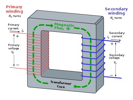
A single-phase transformer is an electrical device designed to convert magnetic energy into electrical energy. It comprises two distinct electrical coils, known as the primary winding and the secondary winding. The primary winding is responsible for receiving electrical power, while the secondary winding is responsible for delivering it. These coils are typically enclosed within a magnetic iron circuit, referred to as the "core," which serves to magnetically link the two coils.
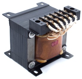
The operation of a single-phase transformer is initiated by passing an electric current through the primary winding. This current generates a magnetic field, which, in turn, induces a voltage across the secondary winding. The primary purpose of a single-phase transformer is to either step up or step down the voltage at the output, depending on the specific application. These transformers are commonly employed in power distribution and transmission due to their high efficiency and minimal energy losses. Below, you'll find an illustration of the typical single-phase transformer diagram.

Single-Phase Transformer
Principle of a Single-Phase Transformer
A single-phase transformer operates based on the fundamental principle of Faraday's Law of Electromagnetic Induction. The core concept behind the operation of an electrical transformer is the phenomenon of mutual induction, where there is an interaction between the primary and secondary windings.
Operation of a Single-Phase Transformer
A transformer is a static device that facilitates the transfer of electric power from one circuit to another, all while maintaining the same frequency. It comprises primary and secondary windings, and its operation relies on the principle of mutual inductance.
When an alternating current (AC) supply is connected to the primary winding of a transformer, an electric current flows through the coil, creating a magnetic field. This process is known as mutual inductance, and it conforms to Faraday's Law of Electromagnetic Induction. As the current in the primary winding increases from zero to its maximum value, the magnetic field intensifies, characterized by the rate of change in magnetic flux, denoted as dɸ/dt.
An electromagnet generates magnetic lines of force that extend outward from the coil, creating a path for magnetic flux. The magnetic flux links the turns of both windings, resulting in the formation of a magnetic field in the core. The strength of this magnetic field is determined by the number of turns in the winding and the magnitude of the current passing through the coil. Notably, the magnetic flux and current exhibit a direct proportionality, meaning that as one increases, so does the other.

Working-of-Single-Phase Transformer
As magnetic lines of flux circulate around the core, they intersect with the secondary winding, leading to the induction of voltage across it. This phenomenon is described by Faraday's Law, which quantifies the induced voltage across the secondary coil with the following formula:
N * dɸ/dt
In this equation, 'N' represents the number of coil turns.
The frequency remains constant in both the primary and secondary windings of a transformer. Consequently, the induced voltage is identical in both windings due to the shared magnetic flux that links them together. Moreover, the total induced voltage is directly proportional to the number of turns in the coil.
For the sake of illustration, let's consider a transformer with a single turn in both the primary and secondary windings. Assuming no losses, when current flows through the coil, it generates a magnetic flux and induces a voltage of one volt across the secondary winding.
In an AC power supply, the magnetic flux varies sinusoidally, expressed as:
ɸ = ɸmax * sin(ωt)
The relationship between the induced electromotive force (emf), denoted as 'E,' in a coil with 'N' turns is given by:
E = N * (dɸ/dt)
E = N * ω * ɸmax * cos(ωt)
E_max = N * ω * ɸmax
E_rms = N * ω / √2 * ɸmax = 2π / √2 * f * N * ɸmax
E_rms = 4.44 * f * N * ɸmax
Here,
'f' represents the frequency in Hertz, calculated as ω/2π.
'N' is the number of coil windings.
'ɸ' signifies the amount of flux in Webers.
The equation above is known as the Transformer EMF Equation. For the primary winding of a transformer, the emf 'E' is determined by the number of primary turns (NP), while for the secondary winding, the number of turns 'N' is (NS).
Construction of Single-Phase Transformers
A simple single-phase transformer consists of two windings wound cylindrically on a soft iron limb, creating the essential magnetic circuit known as the "transformer core." This core provides a pathway for the magnetic field to induce voltage between the windings.
A simple single-phase transformer consists of two windings wound cylindrically on a soft iron limb, creating the essential magnetic circuit known as the "transformer core." This core provides a pathway for the magnetic field to induce voltage between the windings.
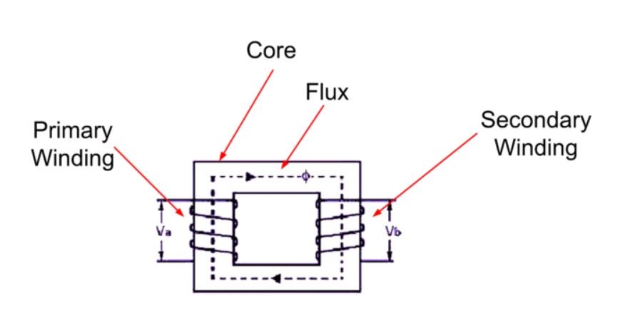
Core-Type Transformer
In this construction type, one-half of the windings are cylindrically wound around each leg of the transformer, as shown in the figure. This design ensures that magnetic lines of force flow across both windings simultaneously. However, it may result in leakage flux due to a small proportion of magnetic lines of force escaping outside the core.

Core-Type Transformer
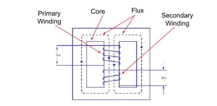
Shell-Type Transformer
In this construction, the primary and secondary windings are positioned cylindrically on the central limb, resulting in a doubled cross-sectional area compared to the outer limbs. Two closed magnetic paths are created, and the outer limb carries half of the magnetic flux, ɸ/2. This design overcomes leakage flux, reduces core losses, and increases efficiency.

Shell-Type Transformer
Applications
Single-phase transformers have various applications, including:
- Stepping down long-distance signals to support residential and light-commercial electronic devices.
- Voltage regulation in television sets.
- Power step-up in home inverters.
- Supplying power to non-urban areas.
- Electrical isolation between two circuits, with the primary and secondary windings placed at a significant distance from each other.

