Our Blogs
Three-Phase Transformer: Construction and Its Working

The three-phase system plays a crucial role in generating, transmitting, and distributing electrical power efficiently. It caters to the substantial power demands of industries and commercial establishments. To achieve this, three identical single-phase transformers are interconnected or consolidated onto a single core, forming a robust three-phase system. Depending on various industrial requirements, both step-up and step-down transformers find application in power generation, transmission, and distribution. The construction of a three-phase transformer unit proves cost-effective as it requires fewer materials when compared to connecting three individual single-phase transformers. Moreover, the three-phase system predominantly transfers AC (alternating current) power, which is simpler to construct and maintain than DC (direct current) systems.
Understanding Three-Phase Transformers
In electrical engineering, a single-phase transformer is a device designed to transfer electrical energy from one circuit to one or more other circuits through the principle of mutual induction. It comprises two essential coils – a primary coil and a secondary coil – which facilitate the conversion of electrical energy. The primary coil connects to a single-phase power supply, while the secondary coil links to the intended load.
On a similar note, a three-phase transformer extends this concept to three primary coils and three secondary coils, denoted as 3-phase or 3ɸ. The creation of a three-phase system can be achieved through either utilizing three individual, identical single-phase transformers, collectively referred to as a "bank of three transformers," or by integrating the three-phase transformer into a single core. The windings of a three-phase transformer can be interconnected in either delta or wye configurations to suit the specific application.
The operation of a three-phase system parallels that of a single-phase transformer, and these multi-phase transformers find extensive use in power generation plants to efficiently manage the distribution and transmission of electrical power.
Construction of Three-Phase Transformers
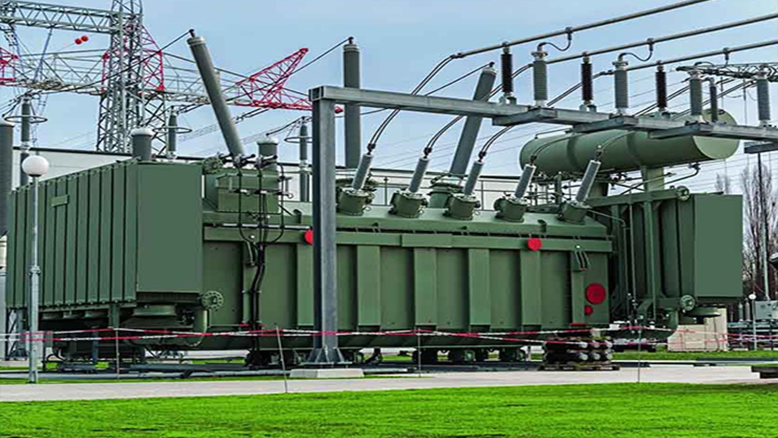
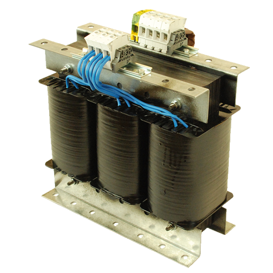
The illustration below depicts the configuration of a three-phase transformer.
Three-phase transformers in a single unit are widely preferred due to their lightweight nature, cost-effectiveness, and space-saving advantages over banks of three individual single-phase transformers. The construction of three-phase transformers falls into two primary categories: Core type and Shell type.

Three-Phase Transformers
Core Type Three-Phase Transformer
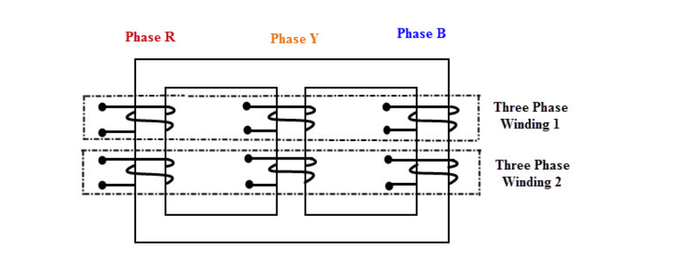
In the core type construction, there are three cores and two yokes. Each core possesses both primary and secondary windings, which are spirally wound, as illustrated. Each leg of the core accommodates both high voltage (HV) and low voltage (LV) windings. To minimize eddy current losses in the core and yoke, the core is constructed with laminations. Given that it is more practical to laminate low voltage windings, these windings are positioned closer to the core. Suitable insulation and oil ducts are incorporated between the low voltage windings. Meanwhile, the high voltage windings are situated above the low voltage windings and also feature adequate insulation and oil ducts for cooling and insulation purposes.

Core Type Three-Phase Transformer
This core type construction ensures an efficient and compact design, making it a popular choice for various power distribution applications.
Shell Type Three-Phase Transformer
The three-phase shell type transformer is typically constructed by assembling three separate single-phase transformers. In contrast to the core type transformer, the shell type design allows each of the three phases to have an independent magnetic circuit. These magnetic circuits run in parallel to each other, and the flux induced by each winding is in phase with one another.

Shell Type Three-Phase Transformer
The shell type transformer is favored for its ability to provide less distorted voltage waveforms. This makes it a popular choice in applications where maintaining a clean and consistent power supply is critical. The independent magnetic circuits and synchronized flux induction in each phase contribute to the stable and reliable performance of shell-type three-phase transformers.
Three-Phase Transformers Working
In the diagram below, a three-phase transformer is depicted, with three cores positioned at 120 degrees from each other. This simplified representation only illustrates the primary windings and their connection to the three-phase power supply. When the three-phase power supply is energized, it causes currents IR, IY, and IB to flow through the primary windings, individually inducing fluxes ɸR, ɸY, and ɸB in each core.
The center leg of the transformer assembly combines all the fluxes from the three cores. It effectively carries the sum of these fluxes, resulting in a comprehensive magnetic circuit for the transformer.
For instance, in a balanced three-phase system where the sum of the currents (IR + IY + IB) is zero, this equilibrium extends to the fluxes as well. Consequently, the sum of the three fluxes also becomes zero, and the center leg carries no net flux. This means that, under these conditions, removing the center leg from the transformer design has no significant impact on its performance. It highlights the versatility of three-phase transformers and their ability to adapt to various operating scenarios, including situations where the center leg might be omitted without adverse consequences.
Advantages of Three-Phase Transformers
Space Efficiency: Three-phase transformers require less space for installation, making them a preferred choice in areas with limited real estate. They are particularly beneficial for urban installations where space is at a premium.
Lower Weight and Reduced Size: Three-phase transformers are typically lighter and more compact than their equivalent single-phase counterparts. This makes transportation and installation easier and more cost-effective.
Higher Efficiency: Three-phase transformers often exhibit higher efficiency in transforming electrical energy, resulting in reduced energy losses during operation. This can lead to energy cost savings and environmental benefits.
Cost-Effectiveness: Their compact design, higher efficiency, and reduced material requirements contribute to cost-effectiveness, making them a cost-efficient solution for power distribution.
Lower Transportation Costs: The reduced weight and size of three-phase transformers translate to lower transportation costs, as they are easier to transport to their installation sites.
Disadvantages of Three-Phase Transformers:
Common Core Dependency: One notable disadvantage of three-phase transformers is that if a fault or failure occurs in any one unit of the transformer, it can lead to the shutdown of the entire unit. This is because they share a common core, and a fault in one phase can affect the others.
Higher Repair Costs: When a fault or damage occurs in a three-phase transformer, the repair costs can be relatively high, especially if it involves the core or complex winding systems. This can result in increased maintenance expenses.
Cost of Spare Units: Acquiring spare units for three-phase transformers can be expensive due to their specialized design and the need to match the existing units precisely. This can increase the overall cost of ownership and maintenance.

